Most digital tv antennas are uni-directional. What this means is that to get the best reception, you must point most digital antennas in the direction of the television station broadcast antenna. To assist the public, the Federal Communications Commission(FCC) and a number of other websites have composed web based tools that allow viewers to enter their address into an online form. Based on the information entered, the website returns the stations that should be accessible from that location, as well as the direction that a uni-directional antenna should be turned to in order to get the best reception. According to where you live, this may require you to point your digital antenna in a number of different directions in any given day.
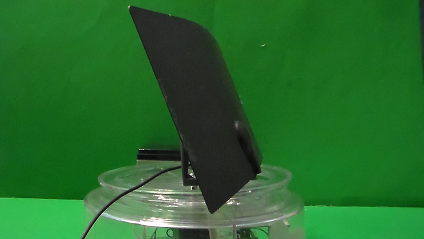
The project in this post will alleviate the need to manually turn your antenna to maximize your TV channel reception and channel strength. Once major potions of the project have been tested, you will need to enter the channels and directions that you obtain from the FCC website and similar websites (antennaweb,org) into the code. Upload the code to the device. After that is done, antenna direction can be changed via Bluetooth capable cell phones and tablets without leaving the comfort of your couch or bed. Below are the pictures of my final antenna mount with the antenna on it.


Follow the videos and instructions below to begin building this antenna mount. Each video contains a full description of the design, decisions, and testing.
Project Video Series: Six parts plus unboxing videos of key parts
Part 1: 42BYGHM809 Stepper Motor Testing (Optional)
In the first installment, you will learn to test your stepper motor and motor driver. You will control the stepper motor with a potentiometer. When the potentiometer is turned clockwise, the stepper motor’s shaft turns clockwise. When the potentiometer is turned counter-clockwise, the stepper motor turns counter-clockwise.
Follow part 1 in the video series to connect and test your stepper motor.
Note: The original circuit design and project can be found on the Arduino website: Stepper Motor Knob.
Part 2: Precision Stepping with the 42BYGHM809 Stepper Motor (Optional)
In the second installment, you will learn to control the angular speed (rpm) and control movement. For precision movement, I will try to turn the motor by exactly a quarter turn (90 degrees) at a time.
Hardware Required:
All of the circuit components that are used in part 1 are also used in part 2, with the exception of the 10KΩ potentiometer.
Equipment Required
The same equipment used in part 1 is also used in part 2.
Software Required
Part 3: Motor Driver Change Justification (Optional)
In the third installment, I explain why you will not be able to turn the motor by exactly a quarter turn (90 degrees) at a time using the circuit components in part 2. The circuits in part 2 can be used to turn a motor, but it will be impossible to achieve precision stepping.
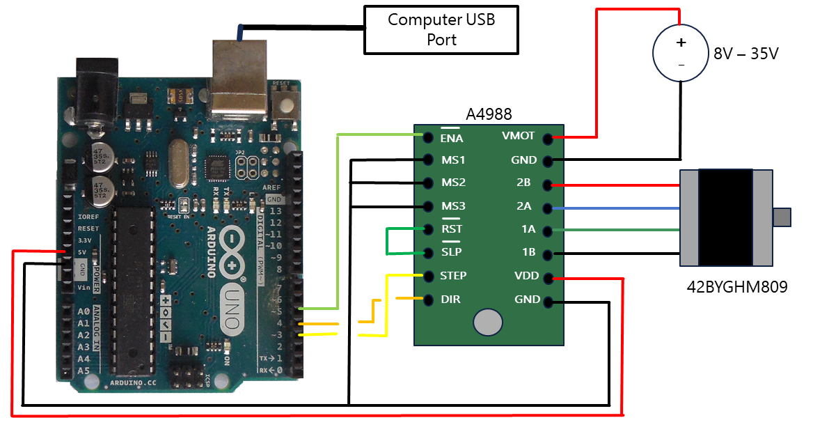
Part 4: Precision Stepping with an A4988 Microstepping Motor Driver
In the fourth installment, you will learn how to perform precision stepping with an Arduino Uno, A4988, and 42BYGHM809 stepper motor.
Hardware Required:
- 42BYGHM809 Bi-polar Stepper Motor
- A4988 Microstepping Stepper Motor Driver
- Arduino Uno
- Connection wires
Equipment Required:
- USB cable
- Computer
- Proto-typing board
- Power Supply
- Small Phillips screwdriver
Circuit
Software Required
Television Transmitter Antenna Locator Websites
You may need to search a number of websites to find the TV transmitter antennas in your local area. Below is a list of websites that I used to find the antennas in my area:
Part 5: Adding a HM-10 Bluetooth Module
In this fifth installment, you will learn how to communicate with the Arduino using the HM-10 Bluetooth module. Communicating with the Arduino via the HM-10 Bluetooth Module will give you the ability to wirelessly turn the motor a specific number of steps, in a specific direction.
Hardware Required:
- 42BYGHM809 Bi-polar Stepper Motor
- A4988 Microstepping Stepper Motor Driver
- HM-10 Bluetooth Module
- Serial Bluetooth Terminal App
- Arduino Uno
- Resistors 1KΩ and 2KΩ*
- Connection wires
Equipment Required:
- USB cable
- Computer
- Cell phone or tablet with Bluetooth
- Proto-typing board
- Power Supply
Circuit

Software Required
- Arduino IDE
- Serial Bluetooth Terminal app**
- Remote Channel Stepping Via Bluetooth
Notes:
* In the video, I use a 1.8KΩ resistor instead of the recommended 2KΩ resistor. The reason was explained in part
** I use the Serial Bluetooth Terminal App from the Google Play Store
Part 6: Antenna Mount Construction and Power Supply Design
In this sixth installment, I create a power supply to power an Arduino and a 42BYGHM809 stepper motor. I also modify a Lazy Susan to work as the mount for the antenna.
Hardware Required:
- 42BYGHM809 Bi-polar stepper motor
- A4988 Microstepping stepper motor driver
- HM-10 Bluetooth Module
- Arduino Uno
- Perforated circuit board without copper cladding
- Resistors 1KΩ and 2KΩ*
- 120VAC to 8-25VDC Power adapter***
- Capacitors 0.22uF**, (2) 0.1uF
- LM7805 Voltage regulator
- LM340T-12 Voltage regulator
- Connection wires
- 30 gauge wire
- Wire-wrap terminal large enough to hold power supply and misc. parts
- Matching DIP component carrier for wire-wrapping terminal
- Lazy susan or some other item that may be used as a base/mount
- M3 Standoffs
- M3-0.5 x 12 mm Machine screws
- M3-0.5 x 6 mm Machine screws
- M3-0.5 Hex nuts
- 5mm Flange Shaft
Notes:
* In the video, I use an old Dell computer power adapter. The output is 19VDC. The reason is fully explained in the video.
** In the video, I use a combination of capacitors to equal 22uF.
Equipment Required:
- USB cable
- Computer
- Cell phone or tablet with Bluetooth
- Small Phillips screwdriver
- Wire-wrapping tool
- Dremel or equivalent with cut-off disks
- Drill bits
- Soldering Iron
- Solder
Power supply circuit schematic

Remainder of the full circuit

Software Required
- Arduino IDE
- Serial Bluetooth Terminal app**
- Digital TV Antenna Direction Finder
If and when new channels are added in your area, simply add the new channel information to the program, upload, and you are ready to change the direction of your antenna while relaxing in your comfy chair.
Possible Additional Adjustments
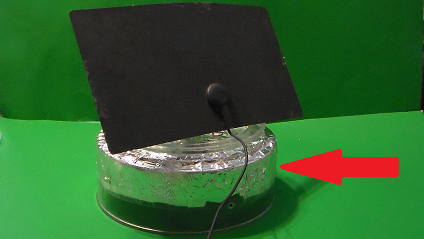
The electronic circuitry placed in the mount may affect the reception of weak signal stations. To combat this, you may need to make an adjustment to the design.
- One adjustment that can be made is the addition of aluminum foil to outside of the base as shown in the picture below. The aluminum could act as a shield to keep some of the electromagnetism generated by the circuit from combining with the incoming signal.
- If you live around tall structures (example tall buildings in a metro area or mountains), you maybe able to receive signals for certain channels at different locations than the locations posted on the websites mentioned above. The reason for this is called multipath. This phenomenon occurs when electromagnetic waves bounce off different structures in multiple directions before getting to your antenna. The different paths could cause interference and, in some cases, lead to poor signal quality.
- When using the scan feature on your TV to find new channels, disconnect the power from the unit to minimize the electromagnetic noise from the system after positioning the antenna.
As I learn more about the antenna, I will post additional information about adjustments that you can make to improve your results.